Thursday, June 30, 2011

Conveyor Supports

Here I've mocked-up the Coal Dump and Conveyor to the transfer House. When I placed the supports that came with the kit under the Conveyor, they seemed to take up too much ground space. I wanted to be able to fit at least one line of track between them, which meant they needed to be farther apart.


Here are the supports as they come in the kit. I figured if I made one taller and the other shorter, they could be placed far enough apart to allow a line of track to fit.


I cut off the concrete piers from the bottom of both, then removed the bottom section of the shorter one, then finally separated the two H-beams.


Finishing the short support was easy, simply re-gluing the piers to the bottom. Those machinist's blocks sure are handy.


The taller support took a few more steps. Using a straight-edge, I glued the H-beams from the short support to the bottom here. The cross-beams were too small to be salvaged, so I made new ones from .060 x .060 styrene. A little cutting and filing, and they match up pretty well.


While waiting for glue to dry, I worked on this, the control room for the Coal Dump. The sides are leftovers, while the door, windows, and roof are Pikestuff.  You can see the roof detail pretty well in this shot.


Sadly, after fitting the altered supports back under the Conveyor, there was still not enough separation to allow a track  through. But by turning them nearly 90° (remember, the Conveyor is at an angle from the Coal Dump to the transfer House) and trimming the tops to fit, I'll gain the space I needed.


Have to say I'm having a lot of fun. Hope you're enjoying it too.  Don

Transfer House Pt.2

When I was cutting all the pieces for this, I worked hard to make sure they were all nice and square. That work paid off, as the assembly went very smoothly. Here are some pictures that show the steps I took. The magnetic jig came in handy.


Here I've added the roofs, made of Pikestuff corrugated roofing (a later posting will show more detail of this excellent product )...........


......and a walkway out of plain styrene.


I determined the Transfer House needed to be about 10" tall, so I cut two 9/32" H-beams the required length to give that height, and glued them to the short sides at the top of the photo. Next I turned my attention to  the longer H-beam that needed to be cut to the same angle as the.........hey wait a minute, where did the roof go? And the walkway? The roof and walkway weren't wide enought to cover the the tops of the H-beams. SOOOOOOO..................


I cut a new roof wide enough to cover. As for the walkway, I didn't feel one was necessary there, so I cut two thin triangles of styrene to give a slight slope, and slapped a roof on there.


Actually, you can get a pretty good look at the Pikestuff roofing in this shot.


There still needed to be a way into the building, so I installed a door in the bottom side. (Pikestuff, again.)


The base is a storage room made with more of the mine kit leftovers. The double doorway? Like you don't know.


Until someone comes up with a practical pair of Anti-Gravity Boots, there needs to be a platform for the door, and a way to access it. I cut short sections of beam and cantilevered them over the main  H-beam, which support  ................... 


........a platform of styrene treadplate, Plastruct railings, and a Walthers' caged ladder.


Here you can see the Transfer House's position in relation to the Crusher......


......and vice-versa.


One late addition are the X-braces for the main uprights. Might need some more gussets.


That's all for now. Thanks for looking.  Don

Tuesday, June 28, 2011

Transfer House Pt.1

Where the Crusher has to be and where the Coal Dump will fit are going to be hard to connect with a single run of conveyor. So it looks like a transfer house is in order. I began by looking through my 'Coke Oven Leftover Spare-parts Drawer' for any pieces that might provide a suitable starting point. ( I try to keep any leftover parts separated by kit, making it easier to find things when I ned them.) As of now, my Oven Complex is made up of three Walthers' kits, so at one time I had a ton of spare parts. However, I've raided that drawer many times, and now the only pieces I have left in any quantity are the ones that make the Quench Tower. (These will make a fine retaining wall, but that is a project for another day.)  I did find the final two pieces of the panels that make up the top portion of the Crusher. I sat there with them in my hands thinking, "How can I hack these up to suit my needs?" ..........................Well, this is how I hacked them up to suit my needs.


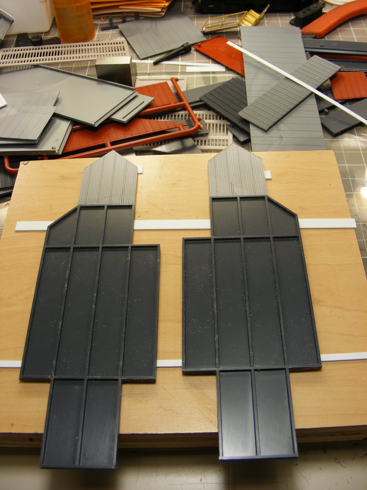
The piece on the left is the un-altered one. Pretty big, huh? I didn't need it or want it to be that massive, all it really does is change the conveyor's direction. On the right is the slimmed-down version, which I hope will be a little more distinctive. One thing to be aware of, this is just the top portion of the Transfer House. It will be supported by a framework of H-beams to the same height as the Crusher, with possibly a storage room at the base. Notice that I removed the top, pointed section , and let me tell you why. It is molded to resemble corrugated siding, and it has a distinctive pattern. The problem is I don't have enough big pieces of that pattern to complete the project. I do have enough big pieces left over from Walthers' New River Mine kit to complete the project, so to be consistant, the tops came off. Now I know you're thinking, "Don, do you really think people would have noticed the difference?," and the answer is, "Probably not." But my thinking is, Hey, I've got this anus, why not be anal once in a while?  Go ahead, argue that logic.


Here I took the cut-off  and used it to scribe the pattern in scraps from the mine kit. The razor saw made short work of cutting them out.


Here they are attached back on top. Just a note to anyone who might be doing something similar. If the opposing sides are irregular, don't forget to make them mirror images of each other.


I cut the walls to the correct size, then used a piece from the original kit to mark the openings for the conveyors. A new blade in the handle, a little patience, and I had some nice, clean holes in no time. (FYI, I like to use X-acto's Stainless Steel  #11 blades. The fact they hold their edge and point much longer make them worth the extra cost.)


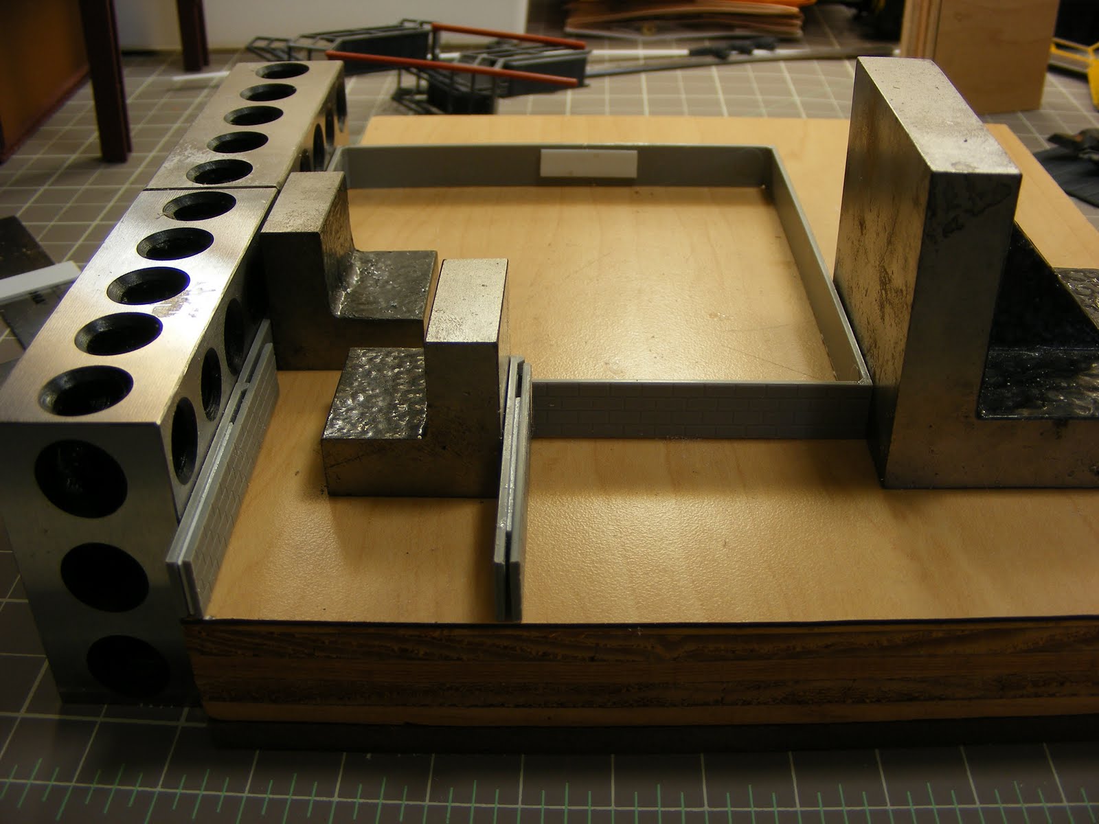
If you need to make repetitive cuts in styrene, you can't beat this jig. Here I didn't even need to use a ruler. As the cut pieces are the same width as the corrugated side, I simply dropped it in the jig and set it flush to it.


Slide the styrene under the bar, tighten it down, then scribe along side it. I've read some people scribe to the outside of the bar, but I scribe on the inside. Works for me, and as I said above, sometimes you don't have to measure.


After cutting them to width above, I cut them to length and wrapped the outsides with .060 x .060 strip. For the internal ribs I placed the assembly over the original piece, to get the proper spacing.


After trimming and sanding, I was left with this. I still have to cut the roof panels, and maybe a walkway. Hmmmmm..... if I had some miniature hinges, I could screw them on and simply fold this together.


That will have to wait for Part 2. Hope you enjoyed this. Don

Monday, June 27, 2011

Crusher

No, not Wesley, COAL crusher, for the coke ovens. When the coal first arrives at the plant, it is dumped through grates into bins, then moved by conveyor to the crusher. There it is reduced to the optimal size for turning into coke. The model I have is from the original Walthers' Coke Oven kit  released in the late '90s. It is an imposing size, but lacks character and detail. This is what I have done the last two days to glam it up.

The first thing I did was add a foundation under it. I used four-course strips cut from a piece of Pikestuff  Concrete Block Walls.  Let me take a moment to say something nice about Pikestuff. If you model or scratchbuild in styrene, and have not used any products by Pikestuff (or Rix), you owe it to yourself to check them out. With crisp castings and fine detail, no warping, and almost no flash, it's a joy to use. Now, back to our program. I just used the base portion of the crusher to determine the dimensions of the foundation. The crusher has a roll-up garage door, which now would need a ramp to access, so I included two retaining walls to contain the ramp.


The glue-up of the foundation. Who'd a thought something as simple as metal blocks would be so useful, but I wonder how I lived all these years without them. The 'L' shaped ones are Machinist's Bocks. All surfaces are at 90° to each adjoining face, and all are dead-flat. The ones with the holes are 1-2-3 Blocks, so called because they are 1" x 2" x 3." All of their surfaces are also 90° to each other, allowing you to square-up your project, while the weight of them holds the parts together while glueing. Here, the small block is holding the center retaining wall hard against the front wall, which is anchored by the large block. Notice the shim between the two pieces that make up each retaining wall, to beef them up.


I thought the crusher needed more than the roll-up door to gain entry, so I cut out a section of wall and added this door.


When I measured the foundation strips, I left the right side long enough to include a concrete walkway under the door, which I made from .030 stock. Square stock at the ends of the retaining walls represent concrete pillars. The two triangular pieces are there to support the sides of the ramp.


The ramp is in, as well as .030 x .125 strip to cap the tops of the retaining walls. A little Squadron green putty fills the joint between the walkway and the ramp nicely. Steps made from Central Valley stairs complete the scene...... for now.


Walthers' kits have a good fit overall, but even when assembled properly, the roof-lines have an unsightly gap. I covered it here with a ridge cap made frome  some thin .010 x .125 styrene. From now on, all roof-lines will meet with  mitered edges or have ridge caps.


The crusher re-assembled. I added an exhaust fan to the side (And tell me why you think it needs to be relocated.). I think the building still needs some things, notably stairways, but those will have to wait  until I determine the conveyor layout.


That's all for now. I hope you enjoyed it, and I welcome any comments. Don


Saturday, June 25, 2011

Slag Pot

I still don't feel 100%, so my modelling has been sparse this week. Mostly I've been playing with those ladles and slag car on the bench.


First, I primed the ladle stand I built last week, and I think the concept holds together pretty well. The thinner gussets sure are an improvement.


I found a picture of a wheeled stand that would move a slag thimble under the overflow spout of a ladle, such as the one above. This is my take on that. First I made two rings of .040 plastic. Note the lower one is smaller than the upper. I then pre-curved a strip of .010 x.250 plastic and glued it to the inside of the upper ring. To beef it up, I wrapped the outside of that strip with two .010 x.125 strips, then trimmed the .250 strip flush with the two .125 strips. Finally, I glued the bottom ring to the assembly. Next came the base. I took two I-beams (.250" I think), came up with a suitable wheelbase, and drilled four small holes equidistant from the ends. Reaming the holes with the Micro-Mark 'Truck Tuner' allows the wheelsets to turn freely. Wheel journal castings cover where the axles protrude through the I-beams.  I cut two more I-beams just long enough to allow minimal play in the wheelsets. Then I glued everything together, nice and square. After that, 4 H-beams join the ring to the base.


Here is the stand holding the slag pot, and with triangular gussets added. NOTE TO SELF: Next time, glue the gussets to the H-beam FIRST. They will be easier to attach precisely, and they will square up the assembly automatically. I had to do a fair amount of filing on the triangles to get a good fit. All I have to ddo now is make a pair of trunions for the pot, so it can be lifted from the stand to the slag car.


I think I'll put the ladles away for a while. I've been promising myself to get back and finish the coke ovens that have been half-finished for a while now, so my next posts should be about that.  Don

Sunday, June 19, 2011

Feedback

I really would like to hear any comment you might have, good, bad, or indifferent. If you wish to leave a comment, click on the appropriate post title to the right , and it will give you a place express yourself. I'm looking forward to your comments or questions.

Don

The Photo-Resist, but I Couldn't

Got my package from Micro-Mark yesterday, and it was like Christmas. Some Caboose throws, and a depth gauge, and some really neat micro-saws the size of a #11 blade (already tried them, work great). But the real jewel was their Photo-Etching System. I really didn't have a specific project that needed photo-etched parts, but I couldn't pass up the low sale price. Damn you, Mass Marketing!  I'm sure something will occur to me, but I am open to suggestions as well, if any of you have any ideas. I went through the instruction manual last night, and it is a lot more involved than I expected. But hell, back in the 70's I used to develop Ektachrome slide film with Kodak's 20-step E-4 kit, so I'm sure I'll muddle through this.

Now if Micro-Mark would really drop the price of a resistance solderer.................

Don

Working With Weights

No, I'm not working on my upper body strength, just trying to get my freight fleet to NMRA standards.  I started by getting an electronic scale that came with stick-on weights. I wasn't wild about the weights, though. They were an awkward size that didn't fit too many places, they were not condusive to being trimmed to fit, and they were not actually heavy for their size. I wanted some sheet lead that I could custom cut to fit specific areas. But due to the bad reputation lead has recieved over the last decade or two, it is hard to locate. I had hoped to find a roll of lead flashing that was used to waterproof a roof valley, under the shingles. I guess they use rubber for that now. Anyway, while walking the roofing aisle at Home Depot, I found some flashing for the pipes that vent your plumbing system, and they appeared to be lead. They come in three sizes for 1", 2", and 3" pipes. Not only do you get more surface area the larger you go, but the thickness increases as well. I went with the the 3" shroud.

The photo on the left shows how all wadded up the flashing will be at the store. The one on the right is after straightening. Please be aware that the base is actually square shaped, I had cut off a 2" strip before taking the picture. A hacksaw makes quick work of removing the tube section, and tin snips disect it. After flattening with rollers and a hammer, I was left with the two pieces below, about 200 square inches.


Let's weight down a difficult car, Walthers' iron slag car, shown below.  Not a lot of places to hide weight on this car. (Sure, sure, I could just fill the thimble with lead, but that's kind of cheating. Besides, I may want to run them empty.)


You can try using a small ruler to measure the cavity sizes, but I like to use a set of precision dividers. Much quicker and more accurate. Here I'm measuring the curved center-beam of the car.........


.....and here I'm transferring to the lead.


I scribe the cut lines with a probe, then finish the cut with a knife. You can use about any kind of knife (this is an x-acto #2), just be aware you will go through a fair amount of blades. You will have a raised lip along the cut line, just run the barrel of the knife down the strip to flatten it.


The lead is easy to form, and a drop of gap-filling CA holds it in place.


Stacking pieces under the ends. Just make sure it can't be seen from normal viewing angles.


The flashing I used cost a little under $20, and will do a dozen or more cars, depending on the manufacturer. The State Tool and Die line of cars are all-plastic and come without weights, so I'll not only show how to weight them, but how I customize them. Coming in a future installment. I hope everyone is enjoying my ramblings.


Saturday, June 11, 2011

What, Me Paint?

I have never tried to hide the fact I prefer the start to a project rather than the finish. In other words, I love the glue and hate the paint. It's not that I hate it, I just was never very good at it. I started with a Paasche single-action, then went to an Aztek double-action, but I never seemed to get the hang of it. Most of the problem was a result of clogging. No matter how much I stirred, shook, or thinned, it seemed the airbrush would clog up in 30-45 seconds. It got so frustrating, I rarely finished a project totally.

One day I'm going through the Micro-Mark mailer and see a motorized hand-held paint mixer on sale, and think, "Why not?" It arrives in a week, I slap in a couple of batteries, grab a bottle of Polly-Scale, and...........

.....Boy, is my face red!  And no, it's not because the mixer splattered paint on it. It's because all those years of frustration and torment were due to never once having used a properly stirred bottle of paint. My stirring by hand for a minute or more didn't come near the results of a 10 second spin of the mixer. Now when I use the airbrush, the only time I stop is to refill the cup.

I won't say I love to paint now, as I still prefer the construction phase, but I sure don't dread it. So, here is my mixer and some accessories I made for it.


I liked it so much, I bought a second. The spinner on the right is how it comes out of the box, which is perfect for probably 90% of the paints out there. But if you use the Vallejo line of paints, it is too big to fit down the narrow neck of their squeeze bottle. However, a little alteration with a Dremel grinding wheel gives you the spinner on the left, which will fit.


I found cutting a small hole in a large prescription bottle and filling it with water (if you use acrylics like me) makes for easy clean-up of the mixer. A quick spin in the bath and it's clean as a whistle. Check with your local pharmacist for a suitable bottle if you don't already take horse pills like me.


When I first introduced this topic on a forum, there was concern by some about splatter. As long as the paddle doesn't break the surface of the paint, it usually isn't a problem. But accidents do happen, so I came up with this. Again using a large prescription bottle, I cut out a quarter segment from the bottom, and contoured the top to fit my fingers. Slide a paint bottle in the bottom. and any splatter is contained. I made a little stand to hold it along with my thinner and the two mixers.


Here is something else on my painting bench I find very useful. Whether you're mixing paints or cleaning an airbrush, you always need water and alcohol handy. I made these two, again using prescription bottles. If you make the holes just large enough for the pipettes, evaporation is not a problem. What is important is to make sure you label the pipette as well as the bottle.